


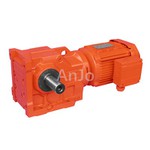
Cycloidal Gear Motor
Cycloidal Gear Motor
A cycloidal geared motor is a power transmission device that integrates a cycloidal pinwheel transmission mechanism as the core reducer with the motor. Its core advantages are compact structure, smooth transmission, and strong overload resistance. It can efficiently complete "speed reduction and torque increase" and is often suitable for scenarios with strict requirements on installation space and torque output.
Features
- High load-bearing capacity and excellent overload resistance: The cycloidal wheel and pin wheel engage with multiple teeth simultaneously, distributing force evenly across multiple tooth surfaces. Compared to helical and spur gears, it can withstand greater impact loads and is less prone to tooth surface damage, making it suitable for heavy-load or instantaneous impact conditions.
- Compact structure and small size: At the same reduction ratio and torque, the cycloidal geared motor is significantly smaller than helical or worm geared motors, and it eliminates complex gear stacking, making it suitable for installation space-constrained environments.
- Smooth transmission and extremely low noise: The multi-tooth meshing method avoids meshing impact, resulting in low vibration during operation and typically lower noise than helical geared motors of the same specifications, making it suitable for environments requiring high quietness.
- Wide reduction ratio range: A large reduction ratio (typically 9:1 - 87:1) can be achieved with a single-stage transmission. With multi-stage combinations, the reduction ratio can be further expanded, meeting low-speed output requirements without complex structures.
Applications
Industrial robots:
Robot joints require reducers that are small in size, have high torque, and high rigidity.
01
Heavy mining machinery:
Tunneling machines, conveyors, and other equipment that need to withstand enormous impact loads.
02
Chemical and pharmaceutical equipment:
Mixers, reaction vessels, requiring continuous and stable operation over long periods.
03
Lifting and transportation equipment:
Port machinery, electric hoists, etc.
04
Injection molding machines:
Require stable and powerful ejection force.
05
FAQ
Q1: What is the most basic principle of a cycloidal geared motor? Why is it called "cycloidal"?
A: Its core principle is cycloidal pinwheel planetary transmission. It's called "cycloidal" because the tooth profile of its core component—the cycloidal wheel—is based on a mathematical curve called a "cycloid."
Q2: What is the fundamental difference between a cycloidal geared motor and a regular geared motor (such as a helical gear)?
A: The fundamental difference lies in the transmission principle and tooth profile.
Regular gears: rely on continuous, line- or surface-contact meshing between gears rotating on a fixed axis for transmission.
Cycloidal pinwheels: rely on the planar oscillating motion of a cycloidal wheel engaging with a ring of pin teeth through multi-tooth, rolling contact for transmission. This principle results in higher torque and greater impact resistance.
Q3: How do I select a cycloidal geared motor for my application?
A: When selecting a model, you need to confirm the following:
Confirm load requirements: Calculate the required maximum operating torque and output speed.
Determine installation method and dimensions: Confirm the installation space—horizontal or vertical installation? Confirm the interface flange size and shaft diameter.
Consider operating conditions: Are there any strong impacts? What are the ambient temperature, dust, and humidity levels like? This relates to the motor's protection rating (IP code) and heat dissipation.
Refer to the selection table and allow for a margin: Based on the calculated torque, consult the manufacturer's selection table, select a model with a rated torque higher than your calculated value, and retain a certain safety factor (usually 1.5 to 2 times) to cope with impacts and fluctuations.
