


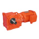
Customized Gear Motor
Product Overview
A customized gear motor integrates an electric motor—AC, brushless DC (BLDC), brushed DC, or stepper—with a mechanical gearbox configured to exact envelope and performance constraints. Eliminating the compromises of off-the-shelf catalog units, these assemblies match specific output torque multipliers, precise ratios, and specialized mounting footprints required for tight industrial enclosures.


Planetary Gear Motors: High torque density, coaxial alignment, low backlash (down to 3 arcmin for precision servo applications).
Spur Gear Motors: Cost-effective for low-to-medium load parallel-shaft configurations; high mechanical efficiency at moderate speeds.
Worm Gear Motors: Right-angle output for space-constrained layouts; inherent self-locking capability preventing back-driving.
Bevel & Helical-Bevel Gear Motors: Right-angle high-efficiency transfer capable of handling heavy shock loads in industrial drives.
Technical Specifications
|
Parameter |
Operating Range / Metric |
|
Output Torque |
0.1 Nm to 500+ Nm |
|
Output Speed |
0.5 RPM to 3,000 RPM |
|
Gear Ratios |
4:1 to 3,000:1 (Multi-stage modular) |
|
Voltage Options |
12VDC, 24VDC, 48VDC, 110VAC, 220VAC |
|
Backlash Tolerance |
Standard <= 1 degree; Precision Planetary <= 3 arcmin |
|
Ingress Protection |
IP40 to IP68 (Submersible / washdown variants) |
Key Features
Optimized Envelope
Tailored housing geometries integrate directly into existing machine castings or mobile chassis frames.
Thermal Management
Aluminum alloy extruded housings with integrated fin profiles dissipate heat under continuous duty cycles.
Custom Shaft Outputs
D-cut, splined, keyed, hollow shafts, or integrated lead screws machined from hardened alloy steel.
Feedback Integration
Optical encoders, magnetic encoders, and absolute position sensors directly mounted to the motor rear shaft.
Mobile Robotics: Drive wheels and steering actuators for Automated Guided Vehicles (AGVs) and Autonomous Mobile Robots (AMRs) operating on 24V/48V DC power.
Medical Devices: Low-noise positioning drives for patient lifts, surgical tables, and automated diagnostic analyzers.
Industrial Automation: Conveyor diverter gates, rotary index tables, and automated packaging feeder mechanisms.
Renewable Energy: Azimuth and elevation tracking actuators for utility-scale solar panels.

Materials & Construction
Gear Metallurgy
20CrMnTi alloy steel carburized and case-hardened to HRC 58-62 for high wear resistance; powder metal or engineered engineering plastics (POM/Delrin) for low-load instrument gears.
01
Housing Construction
Die-cast ADC12 aluminum for lightweight mobile units; FC250 cast iron for heavy-duty industrial gearboxes.
02
Bearings
Deep groove ball bearings and tapered roller bearings sized to absorb radial and axial shaft loads.
03
Lubrication
Synthetic high-temperature grease or ISO VG 220 gear oil selected based on operating temperature and duty cycle.
04
Manufacturing & Quality Control
Hobbing & Grinding
CNC gear hobbing and Reishauer gear grinding machines maintain AGMA Q10 / DIN 6 gear accuracy.
01
Heat Treatment
In-house controlled-atmosphere carburizing furnaces ensure consistent core toughness and surface hardness.
02
Dimensional Inspection
CMM (Coordinate Measuring Machines) verify housing bore tolerances and shaft concentricity within +/- 0.005 mm.
03
Load & Endurance Testing
Dynamometer test benches measure actual output torque, efficiency, current draw, and operating temperature rise under loaded conditions.
04
Traceability
Controlled production lines with laser-etched serial numbers linked to raw material mill test reports (MTRs).
05
Customization & OEM
Mechanical Interface
Custom mounting flanges, pilot diameters, and bolt circle patterns matching existing legacy assemblies.
Electrical Integration
Custom wire harnesses, sealed heavy-duty connectors, and integrated motor driver PCBs.
Environmental Sealing
O-ring face seals, oil seals with dust lips, and vacuum impregnation of motor windings for humid or corrosive operating conditions.
Selection Guide
Define Duty Cycle
Determine if the application requires continuous operation (S1) or intermittent cycling (S3 to S8) to calculate thermal limits.
Calculate Torque Requirements
Multiply peak load torque by a safety factor of 1.5 to account for startup inertia and shock loads.
Verify Space Constraints
Map maximum allowable envelope dimensions (length, outer diameter, shaft extension) to prevent spatial interference.
Specify Environment
Note exposure to moisture, dust, chemical washdowns, or extreme ambient temperatures to dictate IP rating and lubrication type.